IRC Components quickshifter uses a "Strain Gauge" style sensor that is IP65 rated with quick-disconnect plug. We have put an enormous amount of energy in the form of time, technology and knowledge to create a reliable performance-oriented product. This product is encouraged for use on a closed circuit only, is not homologated for road use. IRC is not liable for any injury or damage to the operator, vehicle, or third parties from the use of this product.
DISCLAIMERS

System configuration must only be performed when the motorcycle is at a complete stop and securely positioned on paddock stands.
Incorrect settings may partially or completely compromise system functionality and can cause irreversible gearbox damage.
System calibration and parameter adjustment are the sole responsibility of the end user. Exercise extreme care when fastening or unfastening sensor hardware. The strain gauge is a precision component and must be handled accordingly.
Use of this system is at the owner’s discretion. Any hardware modification, software alteration, harness adaptation, or replacement of individual components may impair system operation, cause injury or damage, and will void the product warranty.
Installation must be performed meticulously and in strict accordance with this manual. Post-installation functional testing is mandatory before riding.
Proper installation is critical to system efficiency and reliability. We strongly recommend that installation and initial calibration be performed by a qualified motorcycle technician or specialist.

High-RPM Downshift Warning: The blipper adds supplementary throttle input during downshifts. If engine RPM is near the redline, the motorcycle ECU may override the blip signal to prevent over-revving and engine damage. This may result in incomplete or failed gear engagement. We recommend initiating downshifts below 80% of maximum rated RPM.
Throttle Position Requirement: The blipper operates only at 0% throttle. Any throttle opening during activation may trigger the motorcycle’s limp-home mode.
CONNECTIONS
2
5
4
3
1
Follow the steps below to install the Blipper system on your motorcycle:
1.1) Fix Main Board on the frame (underseat)
1.2) Load Cell Installation (left side)
1.3) Coils connector installation (undertank)
1.4) Gearshift Connector (left side)
1.5) APS Connector. (left side)
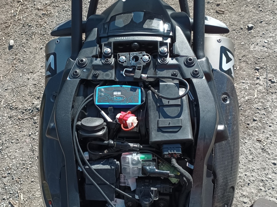
Fix the Main Board on underseat
Secure the main PCB under the rear seat in an easily accessible location, away from high-temperature surfaces (exhaust, cylinder head, etc.).
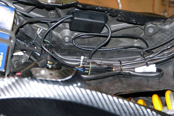
1.2 Connect the Ground Wire
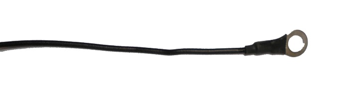
Connect the black ring-terminal ground wire directly to the battery negative terminal. Do not ground to the frame or engine block.
1.3 Load Cell installation
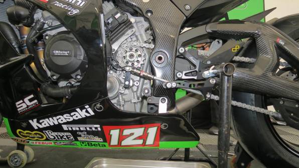
Sensor has “magic threads” i.e. both right and left. Connect the sensor to the shiftrod balljoints.
After alignment, tighten the retaining nuts and secure the grub screws to prevent loosening from vibration.
Route the sensor wire away from hot components. Ensure a slight slack/loop in the wiring harness to prevent tension during gear changes, which could pull or damage the sensor.
Warranty does not cover wire rupture caused by improper routing or tension.
WARNING |
Adjust sensor positioning only via the designated mounting planes. Do not apply force to the sensor cover, as this may cause internal failure. |

1.4 Coils connections
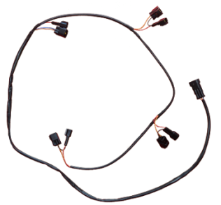
Take the coils harness.
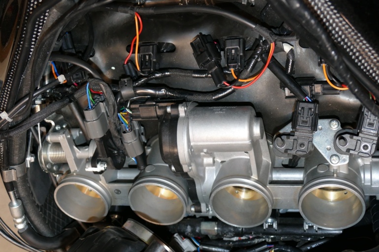
Locate the ignition coils. Unplug the OEM connectors and insert the IRC bypass harness in-line. Order does not matter.
1.5 Gearshift Connector
(Optional but Recommended)
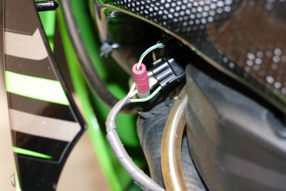
Locate the OEM gear position connector under the left side of the seat. Solder or securely crimp the IRC yellow wire to the central white wire using a proper connector or solder joint with heat shrink.
1.6 APS Connector
Take the APS bypass:
Locate the APS connector near the left side of the cylinder head. Disconnect the OEM plug and install the IRC bypass harness in-line.
1.7 Upshifting connection
Locate the OEM upshift connector on the left side, following the wiring from the stock quickshifter sensor.
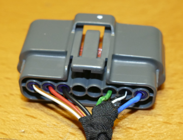
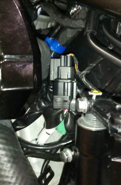
Locate the OEM upshift connector on the left side, following the wiring from the stock quickshifter sensor. Remove the OEM connector and replace it with the IRC bypass cap.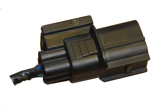
DISPLAY
Upon turning the ignition ON, the system powers up and the ECU performs a self-diagnostic routine.
If the check passes, the display will show the firmware version.
Do not begin configuration, sensor calibration, or parameter adjustment until this routine completes.
On certain Ducati models (referenced in original documentation), “Key ON” may not sustain power; the engine must be running to keep the unit active.
When the preload threshold is exceeded (see Sections 3.4 and 3.7), the display will show --.
In case of a fault, the display will show E followed by a numeric code. Record this code and contact technical support.
SETTINGS
To enter the programming menu, press and hold both buttons simultaneously. Then:
Press the lower button to scroll forward through menus.
Press the upper button to scroll backward.
Press and hold the lower button to enter a submenu. And use upper and lower buttons to modify values.
Press the upper button to save and exit.
The system will automatically exit programming mode if no input is detected (except in the S menu).
The quickshifter function is disabled during programming mode.
|
|
| Parameter | Function | Range / Notes | Default |
|---|---|---|---|
| `t` | Ignition/Fuel Cut Duration | Adjustable: 20–99 ms | 60 ms |
| `rL` | Minimum RPM Threshold | Blip & Upshift inactive below rL RPM setting. Timing scales automatically above this limit. Display scale: /1000. |
02 |
| `SL` | Downshift Blip Timing at rL | Sets blip duration at minimum RPM threshold. | 75 |
| `L` | Upshift Preload Threshold | Customize per rider preference. With ignition ON & engine OFF. Move shift lever upward until gearbox spring resistance is felt. Display shows "—" momentarily. Adjust if trigger occurs too early/late. |
17 |
| `S` | Actual Load Display | Shows real-time applied load on the sensor. Useful for preload tuning and monitoring gearbox wear. | — |
| `S` (Max Load) | Peak Load Capture | Press & hold lower button; “--" blinks for ~10s then displays maximum recorded load during that period. Aids in preload optimization and drivetrain health monitoring." |
|
| `tS` | Downshift Blip Timing at 8,000 RPM | Range: 20–98 ms. At 12,500 RPM, timing increases by +70 ms. CPU interpolates linearly between points. Excessive duration causes post-shift forward push; Insufficient duration causes incomplete engagement. Start high and reduce during track testing. |
85 |
| `LS` | Downshift Preload Threshold | Adjust similarly to L" but in the downshift direction. Display shows "-- when threshold is met. | 14 |
| `CE` | Shift Rod Direction (Push/Pull) | “C" = Pushing (compression) "E" = Pulling (extension). To calibrate: engage 2nd gear, attempt shift to 3rd. Observe shift rod motion. |
C |
| `OC` | Upshifting Circuit Type | “O” = Normally Open (standard for OEM quickshifters & most add-on modules). “C” = Normally Closed (for direct coil cut/UPKIT or Power Commander V compatibility). |
C |
| `1A` | Lower Gear Blip Increase (3→2 & 2→1) | Adds “1A” ms per step to compensate for tighter lower-gear ratios. | 00 |
| `rr` | Shift Smoothness | If OEM or aftermarket upshifter is present, set to 00. Higher values increase damping/smoothness. Set after defining ideal upshift RPM. Display scale: /1000. |
02 |
| `tt` | Firmware/Model Identifier | Do not modify. If accidentally changed, restore to: 14 | 14 |
|
|
QUICK PRESETTING SUGGESTIONS
The system ships pre-configured for safe operation. Only adjust CE (Section 3.8) to enable immediate blip functionality. All default values are conservative. Riders must fine-tune parameters to match their riding style and track conditions.
4.1 Preload Calibration (L & LS)
Turn ignition ON. Do not start engine. Do not touch shift lever.
Enter menu S. Verify display reads 00 or oscillates at 01 (not higher).
Engage 3rd gear. Gently push lever in upshift direction until you just feel gear resistance (do not complete the shift). Note value (08–17 range). Enter into L.
Gently pull lever in downshift direction until resistance is felt. Note value (08–17 range). Enter into LS.
LS should be close to L. Difference must not exceed 2 kg equivalent.
4.2 Blip Timing Calibration (tS & SL)
Focus on gears above 3rd, RPM > 10,000.
If bike pushes forward after downshift → reduce tS.
If downshift is harsh/clunky → increase tS.
Focus on gears above 3rd, RPM ~5,000.
If bike pushes forward → reduce SL.
If downshift is harsh → increase SL.
Test 3→2 and 2→1 downshifts. If harsh → increase 1A.
TROUBLESHOOTING
| Symptom | Diagnostic Steps |
|---|---|
| 5.1 Motorcycle does not start | • Verify UPKIT harness is correctly installed at coils (Section 1.4). • Confirm OC parameter is set to C. • Ensure ground wire is connected to battery negative, not frame. • Check display for E1". If present, contact authorized dealer. Verify sensor nuts/grub screws are tight to prevent vibration-induced failure. • If using LiPo/lightweight battery, test or replace." |
| 5.2 System continuously cuts/blips without lever input | • Verify ground wire is on battery negative. • Secure sensor hardware per Section 1.3. • Test/replace lightweight battery if applicable. |
| 5.3 Blipper works, Upshift does not | • Verify CE setting (Section 3.8). • Confirm battery ground connection. • During upshift attempt display should show "- -" and you should hear a relay click. If not adjust "L per Section 5.1. • Check for E1 code. • Secure sensor hardware. • Verify UPKIT harness installation (Section 4.3/1.4). • Test/replace lightweight battery. |
| 5.4 Upshift works, Blipper does not | • Verify CE setting. • Confirm battery ground. • During downshift display should show "- -" and relay should click. If not adjust "LS per Section 5.1. • Check for E1. • Secure sensor hardware. • Test/replace lightweight battery. |
| 5.5 System operates in reverse | • Verify CE parameter (Section 3.8). |
| 5.6 Limp mode after blip (especially high RPM) | • Confirm APS connection (not TPS). Follow wiring from throttle grip; connect to first available connector (Section 1.5). • Reduce SL and tS values. |
| 5.7 Upshift gears not fully engaging or disengage | • Increase t value. • Verify L setting per Section 5.1. Adjust ±2 points and retest. |
| 5.8 Downshift gears not fully engaging or disengage | • Increase SL and tS. • Verify LS per Section 5.1. Adjust ±2 points and retest. |
| 5.9 Bike pushes forward during blip | • If above 8,000 RPM: reduce tS. • If below 8,000 RPM: reduce "SL. |
WORKING CONDITIONS
11÷17.5V; -20°C÷ +60°C
Enjoy your choice.
For any questions or troubleshooting queries, please contact us at:
tech-support@irccomponents.it • Ph. (+39) 010 8352973